Amazon Packaging Robot
Amazon Package Sorting Solution
For my senior capstone course in the fall of 2021, my teammates and I aimed to create a mechanism to modify part of the organizational system at Amazon to isolate packages and load them onto a robot. Currently, Amazon has workers taking boxes from large mounds at the end of a chute and individually loading the boxes onto an autonomous robot that then takes the box to the correct zip code conveyor belt line. Our intention was to come up with a solution that not only effectively moves boxes but can compete with the speed and efficiency of a worker.
Ideation:
We began ideating our set A in distinct categories. Modify, Isolate, Load. Our course was structured to have a 'set A' ideation category where every member of the team would begin with 'napkin sketches.' Which are rough sketches of an idea that help get the main function across to the other members. The image below on the right side is a sample of my napkin sketches for our set A ideation. The middle image below is a culmination of all of our set A ideas before we settled on our set B ideas. Which is a continuation of set A ideation but with more detail. From our set B ideation, we would take our ideas into CAD and create our set C ideation category. Which would be a collection of CAD files from each member of our team to present to our sponsors at Amazon.

My collection of 'napkin sketches' for our set A ideation.


Board of all of our set A ideas with a handful of napkin sketches. We also had more napkin sketches not drawn on the whiteboard.
After our set A and B ideation, we ran through each of our ideas with a decision matrix to quantify the best idea given our requirements.
After our ideation set A, each team member took their ideas into SolidWorks to present a rough model.
_PNG.png)
My first CAD model of our robot arm. This CAD model did not have a fully fleshed out detailed way of moving the arms or box drop-off area in the back, but it was used to give the general idea I had in mind.
My initial model attempted to capture the main shape and body of the mechanism I had in mind. This mechanism would use rubber-coated wheels on a belt-driven system to grab onto boxes from a pile. Each arm would have functioning 'elbow' joints to allow for reconfiguration depending on the size of the box. Additionally, these arms would have the ability to 'flail' with control to separate collections of boxes from one another. The wheels could then drive and pull the boxes inwards to the end of the table onto a platform that would have the ability to 'release' the single box onto a waiting robot underneath.
Construction/Fabrication
After meeting with our Amazon sponsors, it was clear that the package sorting robot arms were a slightly better option for the goals our team had in mind. With this knowledge, we moved on to constructing our mechanism. Constructing our mechanism required a plethora of parts and precise fitments that we did not anticipate before. To begin, we had to create perfectly press-fitted shafts to fit into our wheels and pulleys. These shafts not only had to fit perfectly with our wheels and shaft but also into a 22 mm ball bearing. We quickly learned that precision tooling requires a lot of time, practice, and attention to detail.
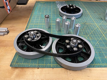
Our construction/fabrication phase was full of many failures and successes. Most of our time was spent brainstorming ways to overcome challenges in our build and waiting for our 3D parts to finish printing. After we mounted the shafts into our wheels and pulleys, we attached them into the bearing case that was a 3D printed part that connects to the extrusion via T nuts. This case would hold the bearing tight and would support the weight of the wheel, pulley, and timing belt. After connecting the wheels and timing belts to each section of extrusion, we moved to join our servos to their respective extrusions. This required a 3D printed part that would connect to a servo mounting bracket. This would hold the servo in place and allow both extrusions to easily screw into the mounting brackets. One issue with this is it causes the servo to be in a compromised position where it can easily tear itself apart if moved too fast or reckless. We found ourselves in this position the night before showcasing the robot to our Amazon sponsors after roughly moving our servos too much in testing. This caused our servo horns to strip and did not allow for two of our servos to work. However, we were able to maintain one of the servos functioning and were able to show the gripping method our robot would use for boxes.
After connecting our servos to extrusions, we realized we were short on time before our showcase and would not have enough time to implement our box-dropping mechanism. This was very disheartening, but we pushed forward to attempt to show the best version of our current mechanism.
Instead of attaching our arms to our initial box-dropping mechanism, I quickly built a small frame out of 30x30mm extrusion.
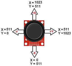
From here, I spent time writing the code to control our motor controllers, motors, and joysticks to drive our system. A small yet cool thing I learned while working on the electrical system for our robot was our joysticks are basically two potentiometers. As someone who grew up playing video games as a kid, this was super neat and helped me make the connection between the physical movements of the joystick to electrical mapping.

Shows the mapping for each plane in the joystick. It shows is basically two potentiometers!


This snippet of code was implemented for showcase purposes. This allowed me to have opposite arms move with a single joystick movement. For example, if the servo moved the top left section of the arm to move outwards, the top right arm section would also move out. So technically opposite directions.
The wiring for our motor drivers/H-bridges and joysticks. Our initial idea was to design a PCB to hold all our components neatly but that is for the next iteration.
_JPG.jpg)
Before lathing the shafts, I drew up a quick drawing to help guide my teammate and I while we machined.

Image of the 3D printed parts that joined our extrusions to a servo. This allowed us to joint two extrusions with a single servo.

Image of the shafts fitted into our wheels, pulleys, and bearings.

Image of our first prototype. This was the first arm. We initially held our wheels to the extrusions with adhesive and our motors to the extrusion with zipties. This was to find the perfect amount of spacing required between the extrusion and wheel motors.
One of the parts of the mechanism that I am most proud of is the code and electrical system. Initially, I planned on being more active in the hardware side of our system. This is why I lathed the shafts for our wheels, but afterward realized I could quickly create our electrical system function as well as the code due to how comfortable I am with Arduino software and motor control. Additionally. I have innate gravitation to electrical systems and enjoy troubleshooting circuits.
My love for electrical systems is so deep that when our team was most stressed towards the end of our deadline, I felt like a child on a pile of legos. Everything was slowly falling into place and I felt in a state of flow where nothing could blur my state of focus.
Showcase
After going through our fair share of moments of glory and sadness, we made it to the day to showcase our project to our sponsors from Amazon Robotics- Tim Martin and Caroline Keely.

Showcase day! Here's our table with our robot on top. We used our personal laptops to present different snippets of our slide show.
To our surprise, Tim and Caroline visited our table first and we got to give them the first pitch of the day. Though I am unable to express how they felt that day, after sharing our project I felt a sense of drive to make our mechanism better. I am sure I was not the only team member who felt this or the only person out of all the other engineering students at the showcase. However, I know I can create a more complex system and should continue this project.
Regardless, our project was working on showcase day and we were able to show it grabbing boxes and sliding them through our robot's body.
The clip shows our robot arms gripping onto an Amazon package and successfully sliding it down it's body towards the end of the table.

Image of our robot the day before the showcase.
Reflection
This project was a blast for my teammates and me. We got to explore new aspects of prototyping and got to grow closer as friends while doing so. I got to practice my passion for electromechanical systems and project planning. From this project, I learned project planning is vital for a large system and it is important to effectively use your teammate's skills for an efficient project timeline.